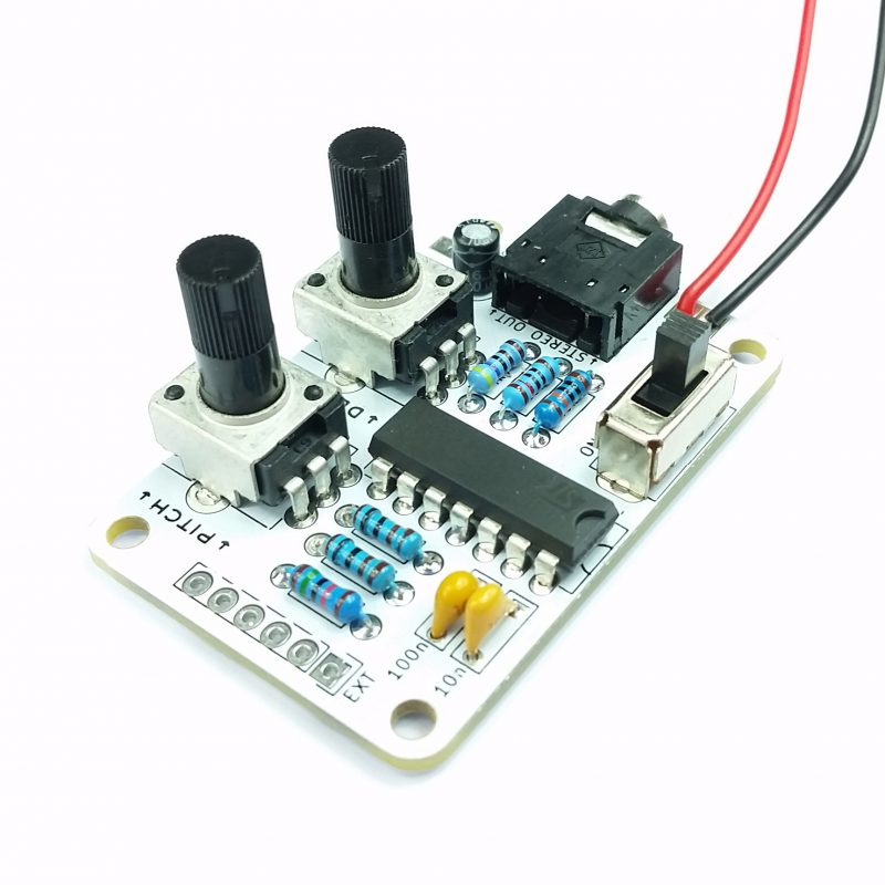
Thank you for purchasing our APC kit!

This is a beginner level kit and should take between 30 minutes and an hour to complete.

This Atari Punk Console kit is based on the original Stepped Tone Generator by Forest M. Mimms III. It creates great lo-fi sounds resembling those from the old style Atari games using an astable square wave oscillator.

If this is your first kit, congratulations! Soldering is a really valuable skill to have in life, but like most things only gets better with practice and experience.

Please tag and share your first builds with us on social media @rakit-kits so we can all bask in the freshly soldered glory.

WHATS INCLUDED IN YOUR KIT

There are a lot of small components included in the kit so please open the packaging carefully and check that all parts are present and correct using the parts list below before you start.

PCB
500k Potentiometer 2
NE556 Dual 555 Timer IC 1
100k Resistor 1
15k Resistor 1
10k Resistor 1
1k Resistor 2
4.7k Resistor 1
10uF Electrolytic Capacitor 1
9V Battery Snap 1
10nF Ceramic Capacitor 1
100nF Ceramic Capacitor 1
On/Off Switch 1
3.5mm Stereo Jack 1

YOU WILL NEED:

Soldering iron, solder and flush cutters

Optional but handy..

Pliers are handy to bend component legs. Blu Tack can be used to keep the circuit board and component in place while soldering. A multi-meter can be used to check resistor values. (See more on this below!)

USING A Multi-meter?

To check your resistors, set your multi-meter to the Ohm (Ω) setting and place the probes across the resistor.

Chances are the resistors will be bang on, or really close to one of the values in the kit. Verify this for yourself by checking the colour codes on the resistors and the provided cheat sheet.

But don’t worry! You definitely don’t need a multi-meter to assemble a kit.

ORGANISE

Organisation… boooo! (But seriously, take your time)

Soldering in a methodical process will set you up for success.  

let's get started!!

Pick a resistor (we started with a 10k).

The components must be placed on their silkscreen outlines on the front of the PCB. Your APC will NOT work if you solder to the back of the PCB!!!!!

Resistors can be placed either way around.

Form the resistor into a U shape and insert it into the board

Gently bend the legs outwards.

https://www.https://www.youtube.com/watch?v=r5pdBmH442w

Lets get to soldering!

Press your soldering iron firmly onto the intersection between the circuit board and the component leg and apply solder.

See the video for a quick soldering demo and for more details check out our Soldering Guide.

All the resistors in a handy slideshow!

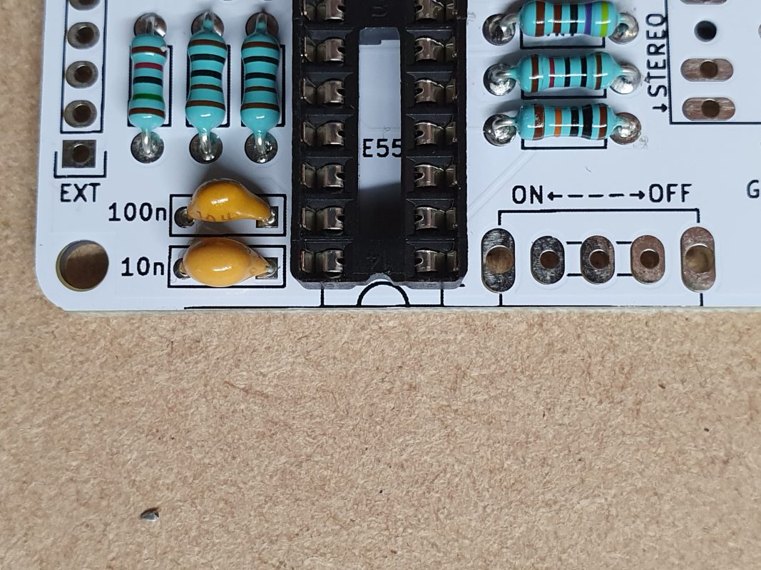
The yellow capacitors are known as ceramic capacitors. The values supplied are 100n (104) and 10n (103). Ceramic capacitors are not sensitive to polarity and can be installed either way around.

Gently bend the legs of the ceramic capacitors outwards before soldering to lock them in place.

Repeat for both ceramic capacitors.

The black cylinder shaped capacitor is called an aluminium electrolytic capacitor (10uF). Aluminium electrolytic capacitors are polarity sensitive and care must be taken to put them in the right way around.

Place the aluminium electrolytic capacitor in the board with the white line facing the filled half of the circle and the long leg in the square pad.

Bend, solder and trim as before.

Insert the chip socket making sure the C shape notch on the socket lines up with the notch on the silkscreen (board markings).

To hold the chip socket in place when turned over for soldering, we like to bend a couple of the legs over slightly, one on opposite corners is enough.

We don’t bend them completely flat purposely, so that trimming is easier later on.

Push the stereo 3.5mm socket into the PCB until it is flush and solder.

Insert and solder your on/off switch.

Either way around is OK, this component is completely symmetrical.

Insert the potentiometers into the board, they should fit snugly into and against the PCB.

Solder your battery snap connector making sure the red wire is connected to V+ and the black wire to GND.

Place your chip the correct way round ready for insertion, lining up the C shaped notch on the chip, socket and silkscreen.

Check that the legs are pointing straight down before pushing the chip in. Often the legs will need a small amount of bending to get them lined up properly.  

Push your chip fully into the socket, being careful not to apply too much sideways force.


That’s it! Your APC is ready for a battery. Plug a stereo cable into your headphones/speakers and create some retro drones. 

Watch the video to your left for a demo of how to use your neighbour torture device APC 

If you have a small speaker or extension header, read on….

When connecting your speaker, simply wire the red wire to the SPK+ and the black wire to the SPK-

Speaker done!

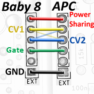
The EXT header socket can be soldered either way around.

We use a small piece of blue tak to hold the socket in place while soldering.

Connect to our Baby8 Sequencer!